Concepts
The terminology and concepts used in lidar2dems is described in the sections below. For more information on point clouds in general, refer to the PDAL and PCL libraries.
Site shapefile
A site shapefile is a shapefile consisting of 1 or more polygons. The polygons should be contiguous, or at least reasonably close together, as the final rasters will cover the region of all the polygons.
The site file serves two purposes:
- Each polygon can be given a CLASS attribute, representing the terrain type which will affect the classification options.
- Each polygon is processed separately, allowing the computation to be done in a piecewise fashion. Final DEM images are created from all of the pieces.
The site shapefile needs be in the Spatial Reference System (SRS) of the LiDAR data, as it is used when setting the SRS of the output rasters. Each polygon in the site file should cover only regions where there is LiDAR data. Areas that fall outside the collected LiDAR area but within the site polygon(s) will suffer from unrealistic interpolation effects during the gap-filling process.
Terrain Types
There are 4 different types of terrain classifications that are used to optimize the ground classification step. Each polygon within the site shapefile can specifiy its own terrain type, which will then use appropriate values for the slope and cell size inputs to the Progressive Morphological Filter (ground classifier in PCL)
1: Flat Non-forest - Relatively flat region with little to no vegetation (slope 1, cell size 3)
2: Flat Forest - Relatively flat region that is forested (slope 1, cell size 2)
3: Complex Non-forest - Varied terrain with little to no vegetation (slope 5, cell size 2)
4: Complex Forest - Varied terrain that is forested (slope 10, cell size 2)
It is important to note that the main advantage of specifying a region as flat versus complex is reduction in processing time, and not in the accuracy of the results. If in doubt of the terrain and processing time is not a concern it is best to use the complex terrain types.
If the site shapefile does not specify the terrain type, default values will be used (slope 1, cell size 3 unless specified at the command line)
Filters
The lidar2dems utilities can take in a variety of optional filters that are used to prune out points.
- decimation: This reduces the total number of points that are processed. This can be useful to greatly speed up processing, if needed for a quick initial product or for testing. A value of 1 indicates no pruning, 2 skips every other point, 3 skips 2, etc. A value of 10 reduces the total number of points by 90%. It is not recommended that decimation be used for final DEM products.
- maxsd: This is the maximum deviation, in standard deviation, points may have. The local average, and standard deviation is calculated for every 20 points. This is useful for filtering out unusually high points (e.g., birds) when creating a DSM.
- maxangle: Every point has an associated scan angle off nadir. This filter will remove points whose scan angle is greater than the maximum angle procided.
- maxz: This is a fixed maximum value for a points Z (height) value. This is useful to remove large groups of unusually high points that would not be otherwise removed by maxsd or maxangle filters.
- returnnum: Each point has an associated return number, which represents the order in which points are returned for a single pulse. First returns are the first reflection off a surface. Later returns are after each subsequent reflection.
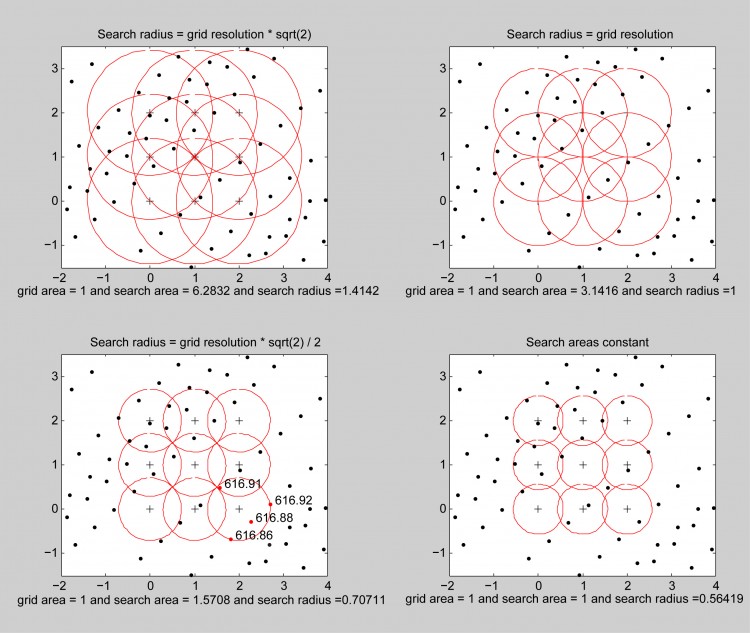
Gridding Radius and Gap-Filling
During the process of gridding, where a raster dataset is generated from a point cloud, a radius is used around the center of each pixel (i.e., grid cell) to identify points used in the calculation of the elevation. The smaller the radius, the fewer points are used, and while it gives an effective higher resolution it also increases the potential for gaps. For DSMs (non-ground) this is rarely a problem, so a value of 0.56 works well. However, for DTMs (ground) in forested areas the data gaps can be significant because of low ground point density.
To help better fill in data gaps, DTMs can be iteratively created using progressively larger gridding radii. When multiple radii are given by the user, final DTM grids will be populated using the output DTM from the smallest radius, and will be “gap-filled” progressively using the next largest gridding radius until all DTM radii are used.
See the points2grid page for more information on how the gridding works.
Interpolation Notes
After gap-filling using all of the available gridding radii, any remaining points are filled with nearest-neighbor interpolation. Additional interpolation options may be provided in the future.
For areas without a high resolution auxiliary DEM: The most appropriate interpolation technique is selected based on void size and landform typology, and applied on the data immediately surrounding the hole, using SRTM30 derived points inside the hole should it be of a certain size or greater. The best interpolations methods can be generalised as: Kriging or Inverse Distance Weighting interpolation for small and medium size voids in relatively flat low-lying areas; Spline interpolation for small and medium sized voids in high altitude and dissected terrain; Triangular Irregular Network or Inverse Distance Weighting interpolation for large voids in very flat areas, and an advanced Spline Method (ANUDEM) for large voids in other terrains.